One o four most important works is conducted in field to help our clients in understanding materials behavior and/or materials limits. TECMETAL prepares microstructural analysis based on replication techniques, where the equipment or structure to be tested in carefully prepared by polishing and revealing the structure by etching, and material structure is reproduced in a plastic tape, called replica.
These replicas are taken to the laboratory and analyzed to understand the material characteristics. These procedures are also supported by other techniques as portable hardness and PMI (portable chemical analysis called “positive material identification”). Some examples are presented in this paper.
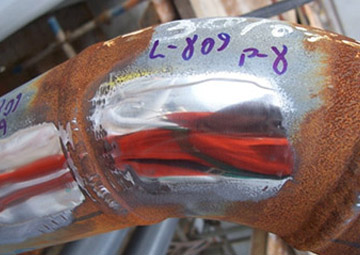
Figura 1 - Low temperature line showing the fitting preparation for microstructural analysis by replica.
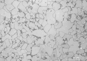
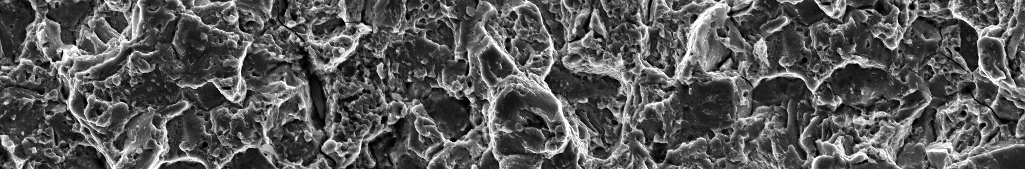
Figura 2 - Ferritic-perlitic structure of a low carbon manganese steel, presenting a refined structure ASTM 9,5 grain size.
Figure 1 presents a polished surface of a C-Mn fitting that should be supplied in the normalized condition in order to be approved for low temperature. Figure 2 shows the material aspect at the microscope. In this case there was a doubt about the material suitability for this special application.
The material grain size should be very fine in order to assure the required toughness, and this fitting presented ASTM 9,5 grain size, which resists to very low temperature and proved to be ok, without destruction of the line, that was ready to run.
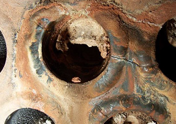
Figura 3 - Crack in a heat exchanger sheet.
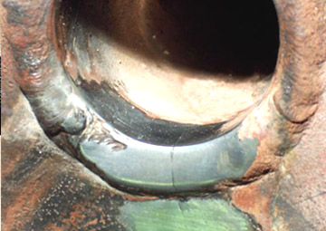
Figura 4 - Heat exchanger sheet after preparation for replica.
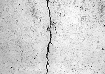
Figura 5 - Replica micrography showing a branch cracking typical of a stress corrosion cracking.
When there is a crack the morphology of the crack makes it possible to understand the mechanism by which the material failed. Overloading, brittle fracture, corrosion, creep, fatigue or wear mechanisms are evident when the starting point of the cracks are analyzed. The problem is that when the equipment requires further repair it is better not to remove a large area for analysis in the lab and again a field evaluation helps a lot to develop repair procedures.
Figure 3 shows a crack in a heat exchanger sheet. After replica preparation (figure 4) and microscope analysis it is possible to see the stress corrosion cracking mechanism, figures 4.
This kind of analysis can be conducted even in large parts or regions of difficult access, as illustrated in figures 6 and 7. And when they are correctly prepared it is even difficult to understand if the structure image was obtained using the replica or the material itself.
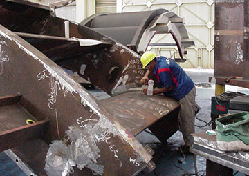
Figura 6 - Hydraulic turbine structure in preparation for replica.
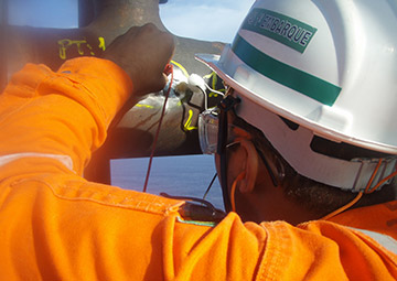
Figura 7 - Flare burning tip in preparation for replica.
Figures 8 and 9 show for a very difficult material to be prepared, a duplex stainless steel, etched using an electrolytic source to reveal the ferritic and austenitic structures, showing little differences between the material analysis image by microscope (figure 8) and the replica image (figure 9).
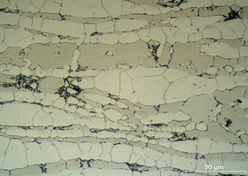
Figura 8 - Mycrography of a material sample electrolytic etched, in a duplex stainless steel, presenting ferrite, austenite and sigma phases.
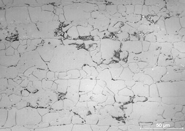
Figura 9 - Micrography by replica after electrolytic etching, in a duplex stainless steel, presenting ferrite, austenite and sigma phases.
![]()
Estrada dos Bandeirantes, 28.000 - Vargem Grande Rio de Janeiro - RJ - CEP 22785-092 | Brasil Fone: (+55 21) 2143 2038 tecmetal@tecmetal.com.br View Map
![]()
![]()


 Portuguese