Cases
Use of Metallographic Replicas
August 2013 · Annelise Zeemann

TECMETAL performs metallographic analyses in the field using metallographic replicas, which are small pieces of plastic that, when pressed onto the area of interest after careful preparation, reproduce the structure by copying the topography obtained by polishing and chemically etching the surface. These replicas are taken to the laboratory and observed as if they were the material itself; in a microstructural analysis, the replica is usually complemented with hardness measurements of the analyzed region, and if the material is unknown, a chemical analysis may also be necessary — all these measurements performed with portable equipment.
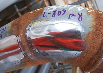
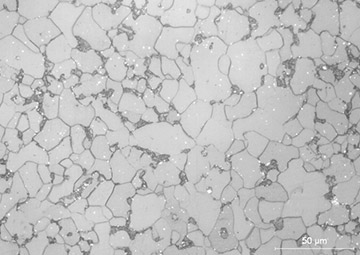
Figure 1 shows a polished surface where a metallographic analysis was performed, and figure 2 shows the appearance of the structure observed under an optical microscope after chemically etching the material (to reveal the structure) and applying the plastic.
In this case, there was doubt as to whether the material of the fitting used in a low-temperature line was a normalized carbon steel, and the grain size measurement of the ferritic structure is essential to ensure the carbon steel's resistance at low temperatures; in this case, the steel had an ASTM 9.5 grain size, corresponding to a very fine grain that withstands low temperatures well.
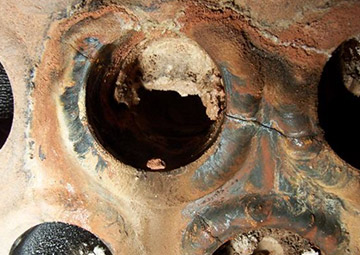
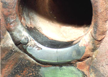
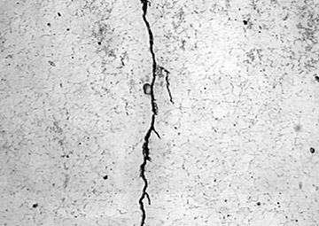
When a crack is present, analyzing its morphology reveals the cracking mechanism, whether it involves significant plastic deformation or no macroscopic deformation, associated with a corrosive process or heat.
Figure 3 shows a crack in a heat exchanger tube sheet that, after metallographic preparation (figure 4), revealed through microstructural analysis that the cracking mechanism was stress corrosion, as shown in the replica micrograph in figure 5.
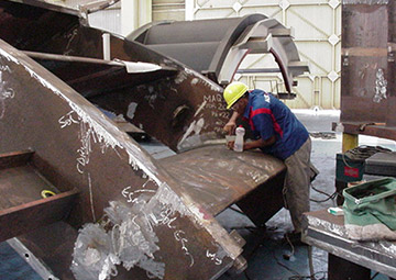
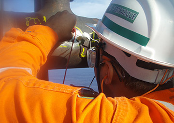
These analyses can be performed on very large parts or in remote locations, as illustrated in figures 6 and 7, and if done well, it's not even possible to distinguish, based on the result alone, whether it is a replica or the material itself being analyzed.
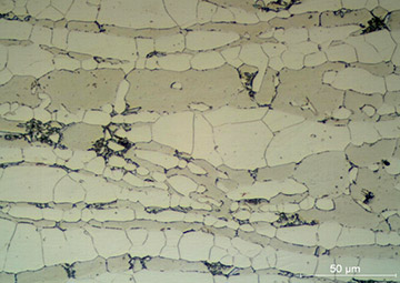
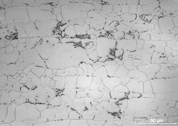
Figures 8 and 9 show, for example, a duplex stainless steel, whose etching is carefully done to reveal the austenite and ferrite phases — in this case still showing the sigma phase — in a micrograph of the material itself (figure 8) or of a replica (figure 9).